
Page 7 - HOLE MAKING CATALOG p311-382
P. 7
USER GUIDE
β¡
ATTENTION: Cutting tools can break during use. γ¡ b
To avoid injury always use safety precautions a
such as gloves, shields and eye protection. REAMERS
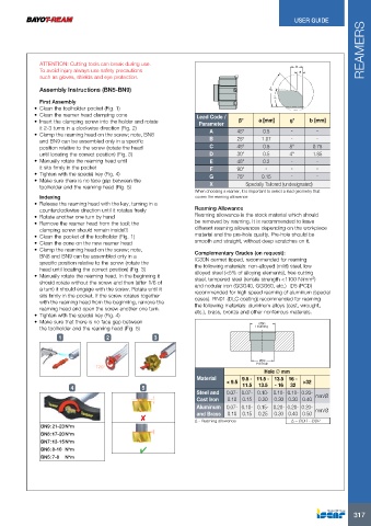
Assembly Instructions (BN5-BN9) Lead Code / β° a [mm] g° b [mm]
Parameter
First Assembly
• Clean the toolholder pocket (Fig. 1) A 45° 0.5 ־ ־
• Clean the reamer head clamping cone
• Insert the clamping screw into the holder and rotate B 25° 1.07 ־ ־
it 2-3 turns in a clockwise direction (Fig. 2) C 45° 0.5 8° 0.75
• Clamp the reaming head on the screw; note, BN8
D 30° 0.5 4° 1.85
and BN9 can be assembled only in a specific
position relative to the screw (rotate the head E 45° 0.2 ־ ־
until locating the correct position) (Fig. 3)
• Manually rotate the reaming head until F 90° ־ ־ ־
it sits firmly in the pocket
• Tighten with the special key (Fig. 4) G 75° 0.15 ־ ־
• Make sure there is no face gap between the
toolholder and the reaming head (Fig. 5) X Specially Tailored (undesignated)
Indexing When choosing a reamer, it is important to select a lead geometry that
• Release the reaming head with the key, turning in a covers the reaming allowance.
counterclockwise direction until it rotates freely Reaming Allowance
• Rotate another one turn by hand Reaming allowance is the stock material which should
• Remove the reamer head from the tool; the be removed by reaming. It is recommended to leave
different reaming allowances depending on the workpiece
clamping screw should remain inside!!! material and the pre-hole quality. Pre-hole should be
• Clean the pocket of the toolholder (Fig. 1) smooth and straight, without deep scratches on it.
• Clean the cone on the new reamer head
• Clamp the reaming head on the screw; note, Complementary Grades (on request):
IC30N cermet tipped, recommended for reaming
BN8 and BN9 can be assembled only in a the following materials: non-alloyed (mild) steel, low
specific position relative to the screw (rotate the alloyed steel (<5% of alloying elements), free cutting
head until locating the correct position) (Fig. 3) steel, tempered steel (tensile strength <1100 N/mm2)
• Manually rotate the reaming head. In the beginning it and nodular iron (GGG40, GGG60, etc.) ID5 (PCD)
should rotate without the screw and then (after 1/6 of recommended for high speed reaming of aluminum (special
a turn) it should engage with the screw. Rotate until it cases). RN01 (DLC coating) recommended for reaming
sits firmly in the pocket. If the screw rotates together the following materials: aluminum alloys (cast, wrought,
with the reaming head from the beginning, remove the etc.), brass, bronze and other nonferrous materials.
reaming head and open the screw another one turn.
• Tighten with the special key (Fig. 4) ReØamDRing
• Make sure that there is no face gap between
the toolholder and the reaming head (Fig. 5)
123
ØDP
Pre-hole
Hole Ø mm
4 5 Material < 9.5 9.5 - 11.5 - 13.5 16 - >32
11.5 13.5 - 16 32
BN9: 21-23 N*m Steel and
BN8: 17-20 N*m Cast Iron 0.07- 0.07- 0.10- 0.10- 0.10- 0.20- mm/Ø
BN7: 13-15 N*m Aluminum 0.10 0.15 0.20 0.30 0.30 0.40
BN6: 8-10 N*m and Brass
BN5: 7-8 N*m 0.07- 0.10- 0.15- 0.20- 0.20- 0.20- mm/Ø
0.10 0.15 0.25 0.30 0.40 0.50
Δ - Reaming allowance Δ = ∅DR - ∅DP
317